|
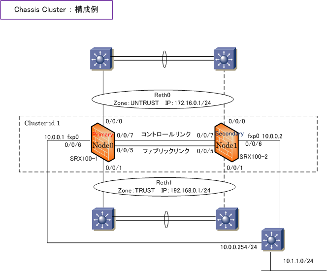
◆ SRX - 冗長化( Chassis Cluster )の設定例
1. オペレーショナルモードでCluster modeへの移行
※ コントロールリンク(fe-0/0/7)を接続した上で下記コマンドを実行します(1号機、2号機の順番でなるべく早く実行)
※ ファブリックリンクは定義していない状態で再起動するので、ファブリックリンクを接続している必要はありません。
【 SRX100-1 の設定 】
| root@SRX100-1> set chassis cluster cluster-id 1 node 0 reboot |
【 SRX100-2 の設定 】
| root@SRX100-2> set chassis cluster cluster-id 1 node 1 reboot |
Chassis Clusterを構成する2台が同一のJUNOSバージョンであれば、上記の実行後、再起動後に cli を入力すれば以下状態へ。
【 SRX100-1 の状態 】
【 SRX100-2 の設定 】
※ この時点でファブリックリンクを接続しましょう。
※ Chassis Clusterを行う2台のSRXのモデルやバージョンが異なる場合、commit 時に以下のようなメッセージが出力されます。
node1:
error: The mime-pattern junos-default-bypass-mime error!
error: The filename-extension junos-default-extension error!
error: The custom-url-category Adult_Sexually_Explicit error!
error: configuration check-out failed
node0:
error: remote commit-configuration failed on node1
error: commit failed
Chassis Clusterを無効化したい場合、両方の機器でオペレーショナルモードで set chassis cluster disable を実行し再起動します。
以降の 2〜6 の設定はPrimary Node(Node 0)のみに設定を行います。設定内容は同期されていきます。
2. fxp0 のIPアドレスとbackup-routerの設定
root# set groups node0 system host-name SRX100-1
root# set groups node0 system backup-router 10.0.0.254
root# set groups node0 system backup-router destination 10.1.1.0/24
root# set groups node0 system service telnet
root# set groups node0 system service ssh
root# set groups node0 interface fxp0 unit 0 family inet address 10.0.0.1/24
root# set groups node1 system host-name SRX100-2
root# set groups node1 system backup-router 10.0.0.254
root# set groups node1 system backup-router destination 10.1.1.0/24
root# set groups node1 system service telnet
root# set groups node1 system service ssh
root# set groups node1 interface fxp0 unit 0 family inet address 10.0.0.2/24
root# set apply-groups "${node}"
|
3. RG0、RG1 では node0 のプライオリティを129、node1 のプライオリティを128としてfe-0(1)/0/0 と fe-0(1)/0/1
をモニター
root# set chassis cluster control-link-recovery
root# set chassis cluster reth-count 2
root# set chassis cluster redundancy-group 0 node 0 priority 129
root# set chassis cluster redundancy-group 0 node 1 priority 128
root# set chassis cluster redundancy-group 1 node 0 priority 129
root# set chassis cluster redundancy-group 1 node 1 priority 128
root# set chassis cluster redundancy-group 1 interface-monitor fe-0/0/0 weight
255
root# set chassis cluster redundancy-group 1 interface-monitor fe-1/0/0 weight
255
root# set chassis cluster redundancy-group 1 interface-monitor fe-0/0/1 weight
255
root# set chassis cluster redundancy-group 1 interface-monitor fe-1/0/1 weight
255
|
4. ファブリックインターフェースの指定
root# set interfaces fab0 fabric-options member-interfaces fe-0/0/5
root# set interfaces fab1 fabric-options member-interfaces fe-1/0/5
|
5. reth0 と reth1 への物理インターフェースへの割当、IPアドレスの割り当て、RG1の割り当て
root# set interfaces fe-0/0/0 fastether-options redundant-parent reth0
root# set interfaces fe-0/0/1 fastether-options redundant-parent reth1
root# set interfaces fe-1/0/0 fastether-options redundant-parent reth0
root# set interfaces fe-1/0/1 fastether-options redundant-parent reth1
root# set interfaces reth0 redundant-ether-options redundancy-group 1
root# set interfaces reth0 unit 0 family inet address 172.16.0.1/24
root# set interfaces reth1 redundant-ether-options redundancy-group 1
root# set interfaces reth1 unit 0 family inet address 192.168.0.1/24
|
6. ゾーンの割り当て、セキュリティポリシーの設定
root# set security zones security-zone UNTRUST interface reth0 host-inbound-traffic
system-services all
root# set security zones security-zone TRUST interface reth1 host-inbound-traffic
system-services all
root# set security address-book TRUST-NW address NW1 192.168.0.0/24
root# set security address-book TRUST-NW attach zone TRUST
root# edit security policies from-zone TRUST to-zone UNTRUST
root# set policy TRUST-TO-UNTRUST match source-address NW1
root# set policy TRUST-TO-UNTRUST match destination-address any
root# set policy TRUST-TO-UNTRUST match application any
root# set policy TRUST-TO-UNTRUST then permit
|
NSRPによる切替りは、数秒以内となります。
それは、reth 0 や reth 0 インターフェース
の障害試験だけでなく、電源障害の試験でも
そのような結果となります。
電源障害の試験方法の注意点となりますが
SRXを再起動させることを電源障害の試験に
するのではなくフロントの電源ボタンを押す
ことで障害試験を実施するようにしましょう。
request system reboot等で再起動しても
正確な電源障害による切替り時間が得られ
ないので注意しましょう。 |
|
【 ステータス確認 】
例えば、TRUSTネットワークからUNTRUSTネットワークへtelnetやSSH通信を行った状態にしておいて
show security flow session を実行すれば Node0 ⇔ Node1間においてセッションの同期を確認できます。
◆ SRX - JSRPの手動フェールオーバー
SRXのJSRPの手動フェールオーバーは以下のコマンドで実現できます。アクティブ機側で実行します。
◆ 実行例 : Redundancy Group 1 と 0 の Primary を node1 にフェイルーオーバー
root@srx> request chassis cluster failover redundancy-group 1 node 1
root@srx> request chassis cluster failover redundancy-group 0 node 1
|
|